Switch Node
Overview
The Switch node is a generalization of the Condition Node to at least 2 cases used to execute one of many sub-flowcharts based on expressions for each case.
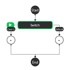
Upon placing a Switch node, generates two sub-flowcharts, ‘Case 1’ and ‘Default’.
Each case has an input ‘Condition: case_x’ which when evaluates to true, causes that case’s sub-flowchart to be executed when the switch node is hit. If multiple cases have conditions evaluate to True, then the smallest number case’s sub-flowchart will be executed (i.e. if Case 1 and Case 2 both have input conditions that evaluate to True, only Case 1’s sub-flowchart would be executed). The Default case’s sub-flowchart will execute when all other cases are evaluated to false.
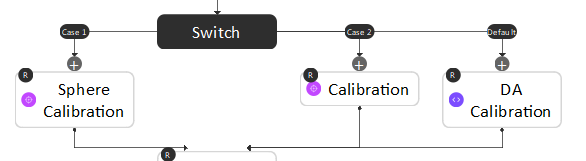
Below is an example of using the Switch node to switch between different calibration types.
Output
Output |
Type |
Description |
|---|---|---|
Condition |
bool |
The boolean value of the input Condition expression. |
Procedure to Use
Set up the flowchart as in the following image.
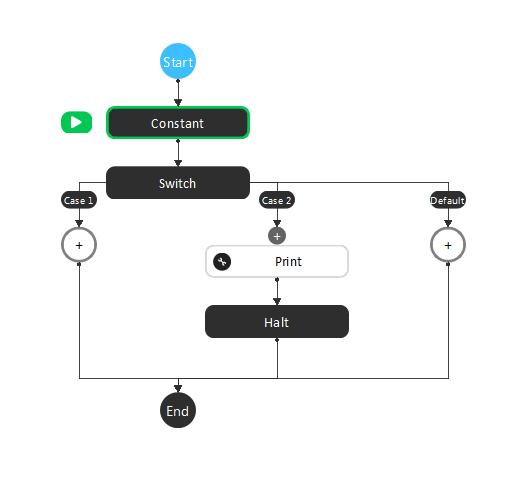
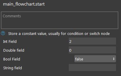
Click the Constant node. Change the Int Field to 2.
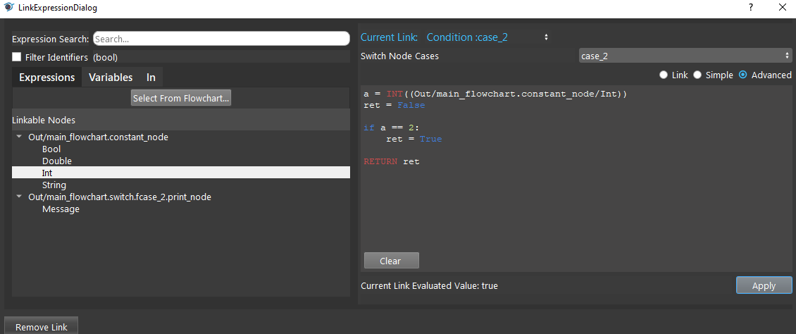
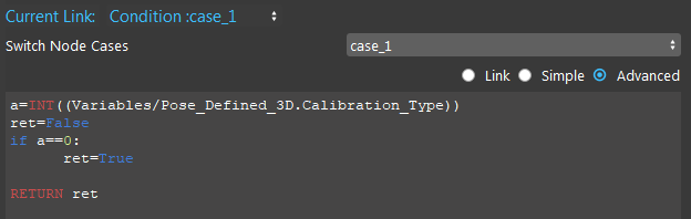
Click the Switch node, select case_2 and Advanced mode. Let condition: case_2 evaluates to True when the Constant Int is 2.
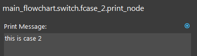
Click the Print node. Type a print message.
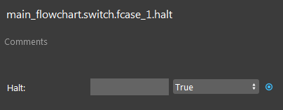
Click the Halt node. Set the Halt value to True.
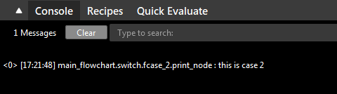
Run the flowchart. You can see the print message from Case 2, and the flowchart is halted.
Exercise
Given there are case_1, case_2, case_3, and case_default. If both case_2 and case_3 are true, which case is run?
case_1
case_2
case_3
case_default
Answers for Exercise
case_2 is run. When two cases evaluate to True, the sub-flowchart of the case with smaller number is run.